1. Product Overview
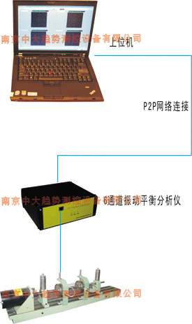
The rotor vibration test stand is a test device used to simulate the vibration of rotating machinery. It is mainly used in laboratories to verify the forced and self-excited vibration characteristics of flexible rotors. It can effectively reproduce the various vibration phenomena generated by large rotating machinery. Through different choices to change the rotor speed, stiffness, mass imbalance, shaft friction or impact conditions and the type of coupling to simulate the running state of the machine, and observe and record its vibration characteristics by the configured testing instrument. Therefore, this test bench provides an effective and convenient experimental method for specialized in vibration testing, vibration research and related laboratories in colleges and universities.
The test stand has a simple structure, a wide speed range, intuitive display, and is stable and reliable. It can realize the stepless speed regulation of the motor from 0 to 10000rpm.
Using the eddy current sensor, magnetoelectric speed sensor, photoelectric sensor or CUT-206 vibration balance analyzer or CUT-408 type vibration acquisition and analysis system produced by our company and the test bench, it can easily depict the Bode plot (width Frequency and phase frequency characteristic curve), vibration mode circle, axis trajectory diagram, frequency spectrum diagram, trend diagram, shaft center position diagram and rate of rise diagram, is a series of rotor test systems very suitable for scientific research, teaching and training demonstration.
Note: In addition to being compatible with CUT-206 vibration balance analyzer and CUT-408 type vibration collection and analysis system, this test stand can also be matched with other data collectors to form a rotor vibration test system. 
2. Composition and main technical indicators
1. Speed ​​regulation range: 0 ~ 10000 rpm, digital display governor: speed display directly
2. Rotor table type: CUT-1 single-span rotor table, CUT-2 double-span rotor table or CUT-3 three-span rotor vibration test table
2.1CUT-1 rotor table: length × width × height: 950 × 150 × 200mm
Number of rotors: 2, Number of rotating shafts: 1, Rotating shaft size: φ10 × 510
2.2 CUT-2 rotor table: length × width × height: 950 × 150 × 200mm
Number of rotors: 2, Number of rotating shafts: 2, Rotating shaft size: φ10 × 270, φ10 × 240
2.3 CUT-3 rotor table: length × width × height: 1250 × 200 × 160mm
Number of rotors: 6, Number of rotating shafts: 4, Rotating shaft size: φ10 × 510 (1 root), φ10 × 270 (3 roots)
3. Basic accessories: oil collecting box and hose, internal hexagonal wrench, oil pot, screw, eddy current sensor bracket, photoelectric sensor bracket, displacement sensor bracket, counterweight disk
4. Optional accessories (optional, optional or optional)
Two or more SE08 eddy current sensors (one each in vertical and horizontal directions, the number depends on the measuring point)
Two or more MT2 or MT20 magnetic or electric speed sensors (one each in vertical and horizontal directions, the number depends on the measuring point)
1 photoelectric sensor
5. Sensor installation
The test stand is equipped with a bracket for installing the photoelectric sensor, and the key phase of the photoelectric sensor can be used.
When measuring absolute vibration, the speed sensor can be installed on the bearing seat of the test stand; when measuring relative vibration, the eddy current sensor can be installed on the eddy current sensor bracket.
6. Experiment: According to the purpose of the experiment, the test bench can be assembled into several different types. Several basic types can be used to: verify the vibration caused by mass imbalance, etc .; verify the oil film oscillation theory; verify the free rotor disturbance can be divided into:
Rotor balancing
2. Rotor's supercritical speed measurement
3. The influence of rotor structure on critical speed
4. Flexible (flexible) vibration mode and friction test
5. Oscillating oil film of sliding bearing
6. Radial vibration and axial vibration of non-contact measuring shaft
7. Bearing seat and table body vibration measurement grass 8. Try to increase the dynamic balance of single-sided, double-sided and multi-sided rotors
9. Vibration monitoring and analysis charts: Bode chart, spectrum chart, trend analysis chart, bar chart, polar chart, axis
Cardiac trajectory diagram, axis centerline diagram, stacked diagram, etc.
10. Misalignment test
kitchen cabinet,modern kitchen, black kitchen,white kitchen cabinets
Guangdong Planet Cabinetry Co., Ltd. , https://www.ptkitchencabinet.com