Overview
At present, the complexity of integrated electronic systems is getting larger and larger, and the stability requirements are getting higher and higher. Therefore, from the beginning of system design, it is necessary to consider the robustness of the system, that is, the fault adaptability of the system. Before the system leaves the factory, for the critical state and functional performance over-limit technical indicators proposed at the beginning of the design, the fault injection system is required to provide the fault test environment for the system's fault adaptability analysis; The use or poor application environment often leads to some unexpected failures. If the fault phenomenon can be reproduced in the laboratory through the fault injection system, the accuracy of the fault location can be improved, and the fault resolution efficiency can be greatly improved.
In order to better and more realistically simulate electronic system failures and maximize the creation of fault environments, Hengrun Technology has developed a fault injection system HiFID.
system introduction

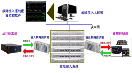
Figure 1 Schematic diagram of the application of the fault injection system
The HiFID fault injection system HiFID creates a fault environment based on the original physical/semi-physical system. It uses string faults between the original interconnected devices and analog lines or interfaces. The fault type is physical layer, electrical layer, The protocol layer is dominant. The fault signals that can be simulated cover almost all electronic signals in the industrial field, and can be divided into bus type, analog quantity and switching quantity according to the type.
From the perspective of system stability, reliability, correctness and safety, it is necessary to carry out fault simulation and fault injection for developing systems and equipment.
The HiFID fault injection system can implement the following fault injection functions:
♦ Defects in the design of system/equipment functions;
♦ Defects in the detection of system/equipment performance design;
♦ Verify system/equipment failure adaptability;
♦ Reproduce faults and assist in fault location;
♦ Diagnose system failures and provide effective means of troubleshooting;
♦ Verify system design and provide a powerful means of system verification.
System composition
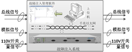
The HiFID fault injection system includes fault injection management software and fault injection equipment. When the fault injection of the train signal is realized, the fault injection device string is connected to the train bus. The fault injection device is controlled by the fault injection management software to implement different fault injection functions.
The fault injection management software runs in a computer or an industrial computer, and controls the fault injection device through Gigabit Ethernet to realize the fault injection function. The fault injection software provides an operation interface for managing the fault items and configuring the fault items.

Figure 3 Schematic diagram of the fault injection system architecture
1, fault injection management software
The fault injection management software is mainly composed of project information management, authority management, fault configuration, equipment control, fault execution, health monitoring, log management, and communication processing module.
♦ The project information management module realizes the function of creating, deleting and managing fault information of engineering information;
♦ Privilege management realizes the permission setting of the project. Users without privilege can not perform any editing function on the project information, only the control of the fault injection device (state readback, self-test) and fault delivery function;
♦ The fault configuration module implements a fault sequence configuration command for the device and monitors the channel status function of the device;
♦ Device control realizes control of self-test, reset, status readback, etc. of the device;
♦ Fault execution implements the function of configuring the fault sequence of the channel of the device, and monitoring the execution status of the channel;
♦ The log management module is used to record the operation of the software on the device and the record of the device failure, and store it in the form of excel;
♦ The communication processing module is configured to send the configuration command to the UDP communication module through the JAVA/JNA calling mode, and the UDP communication module sends the data to the device through the group package, and accepts the state return of the device.

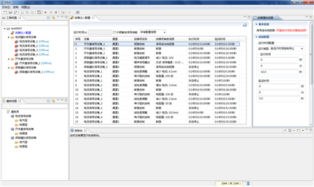
Figure 5 screenshot of the fault injection software
1.2 Fault Injection Function Implementation
• Physical layer fault injection
♦ Signal on/off: configurable signal on/off or periodic on/off failure;
♦ Signal short circuit: configurable signal lines are shorted by two or shorted to other signals (GND/VCC/other signals);
♦ Signal serial impedance control: configurable signal line impedance control;
♦ Signal parallel impedance control: configurable signal line impedance control;
♦ Load Capacitance Control: Load capacitance control of the configurable bus.
• Electrical layer fault injection
♦ Common mode voltage/differential mode voltage adjustment: adjust the signal amplitude of the signal according to the specification to verify the signal recognition capability of the device under test;
♦ Rising edge/falling edge slope adjustment: Adjust the rising edge and falling edge of the signal according to the specification to detect the signal recognition capability of the device under test;
♦ Duty cycle adjustment: adjust the high/low duty ratio of the signal according to the specification, and verify the signal recognition capability of the device under test;
♦ External signal interference: Provide external interface to interfere with the current signal, and verify the signal anti-interference ability of the device under test;
♦ Signal delay: simulate the transmission path of the extended signal according to the specification, increase the transmission time of the signal, and verify the signal processing capability of the device under test;
♦ Protocol layer fault injection.
• Protocol layer fault injection
Protocol layer fault injection of bus signals such as Ethernet, AFDX, RS422, ARINC429, HDLC, WTB, MVB, CAN, etc. according to different bus specifications.
1.3 Introduction to Typical Fault Injection Equipment
• MVB bus fault injection device

Figure 7 Appearance diagram of MVB fault injection equipment
• WTB fault injection equipment

Figure 8 Appearance of the WTB fault injection device
• RS422 fault injection device

Figure 9 RS422 fault injection device appearance
• CAN fault injection equipment

Figure 10 Appearance diagram of CAN fault injection equipment
• Ethernet fault injection device

Figure 11 Appearance diagram of the Ethernet fault injection device
• Analog fault injection equipment

Figure 12 Appearance diagram of analog fault injection equipment
• 0~20mA fault injection device

Figure 13 Appearance diagram of 0~20mA fault injection equipment
• IO (110V) signal fault injection device

Figure 14 Appearance of the IO signal fault injection device
• Power failure injection device

Figure 15 Appearance diagram of the power failure injection device

Skin Care,Ordinary Skincare,Face Cleanser,Face Moisturizer
Homesafe , https://www.homesafebio.com