In a system that uses PLC to implement electrical automation control for automatic die-cutting and creasing machines and other packaged machinery, most of the interlocking control in the classic relay-contactor control system can be transferred to the PLC to achieve relay- The contactor control system is greatly simplified, becoming a MCC (MotorControlCentre) system containing only some necessary electrical interlocks, and becoming a conditional executor of PLC system instructions.
The relay-contactor interlock should be retained
In the integrated design of PLC and relay-contactor system, this kind of interlock mainly refers to important safety interlock, including personal safety and equipment safety. From the perspective of personal safety, some interlocks that are vital to personal safety should be retained, such as accident switches, emergency stop devices, etc. These switches generally require the use of non-semiconductor electromechanical components. From the perspective of equipment safety, it is often necessary to retain some important limit switches and protection methods.
Interface between PLC and MCC system
There are two common methods of interface between PLC and MCC system: one is the method of using relay isolation, and the other is the method that PLC directly receives the signal of MCC system and the PLC directly drives the contactor in MCC.
When the first method is adopted, the signal entering the PLC must first pass through the photoelectric isolation relay, and then its contact point is connected to the PLC input template. The output signal of PLC also drives the relay coil first, and then the relay contacts participate in the MCC interlock control. The advantage of this method is that it facilitates the selection of PLC templates, which may reduce the cost of PLC, basically eliminate the possibility of external strong electricity invading PLC, and effectively ensure the safety of PLC system operation. The disadvantage is that a large number of relays are added, thereby increasing possible new points of failure. In practice, high-quality relays should be used, preferably those with light-emitting devices that can indicate the pull-in action. The advantage of using the direct interface between PLC and MCC system is simple and clear, and the whole control system has few failure points. The disadvantage is that the security of the system is not as high as the first method.
In engineering practice, both methods are widely used, and many systems have both methods. The choice of interface depends on the environment and specific conditions, component level and other flexible considerations and decisions.
1. Human error
1) The solution to the error caused by finger vibration is to use the differential instruction DIFU (13) to retrieve the rising edge of the button to send the electric signal, and the PLC only executes it once in an execution cycle, thus avoiding the occurrence of these types of misoperations, as shown in Figure 1 In the middle, 00005 is the high-pressure pump stop button, HR0005 is the low-pressure pump start flag. When the low-pressure pump start button 00003 is pressed, the signal is converted into a differential command HR0005. HR0005 receives only one rising edge pulse in a program scan cycle, thereby filtering out extra pulses due to finger vibration and ensuring the normal delay of the timer TIM000 1min to ensure that the high-pressure pump starts on time.
2) There are two methods for solving unintentional misoperation. One is to optimize the display function through the program and reduce human errors. In the design, an indicator light is used to display a variety of different working states flat light-the display system is in a running state, high-frequency flashing-the display system is in a test state, flashing 1 every 1s Times; low frequency flash-shows that the system is in a stepping state, flashing once every 3s. The second is through the interlocking between input signals. This method requires a large amount of work and should be considered comprehensively. Otherwise, the input signals will interfere with each other and have a negative effect. Figure 2 is a simplified ladder diagram, 00003 is the start button of the low-pressure pump No. 1; 00005 is the start button of the low-pressure pump No. 2; HR0400 is the sign of the No. 1 host after 24h stop; HR0401 is the sign of the No. 2 host after 24h stop.
2. Mistakes made by the system itself
Due to the complexity of the PLC input signal source, the action response time of the current PLC is much shorter than the response time of the relay contact control system. Therefore, the problem of instantaneous contact jump in the relay contact control system, which will not be noticed, will be in the PLC Misoperation occurred in the control system. For this procedure, interference filtering procedures have been added, see Figure 3.
TIM000 is used to eliminate the instantaneous closing caused by mechanical vibration when the 00104 contact is opened. TIM001 is used to eliminate the instantaneous opening due to the impact of beating and interference when the 00104 contact is closed. CNT020 is used to maintain the input signal. HR0410 and HR0411 are related operating equipment.
When 00104 (oil level lower limit switch) is opened, 00104 is closed momentarily due to the above reasons, and the timer TIM000 is started. If 00104 is opened within the set time, the system determines that the closing is a malfunction and does not execute the following procedure ; If 00104 is still closed within the set time, the system determines that the closure is a normal command, and keeps the input signal through the counter CNT020 to start the related operating equipment; when 00104 is closed, 00104 instantaneously opens due to the above reasons The method is the same as above, the time of TIM000 and TIM001 is set to # 0002 (0.2s), it will not affect the control system. Generally speaking, the setting value of TIM000 and TIM001 time is considered according to the time of the process of immediately disconnecting the input relay after reliable pull-in, about 0.2 ~ 0.5s, within this range, the purpose of eliminating contact jump interference can be achieved . If the time setting value is too large, the system action will be delayed; if it is too small, the effect of filtering interference will not be received.
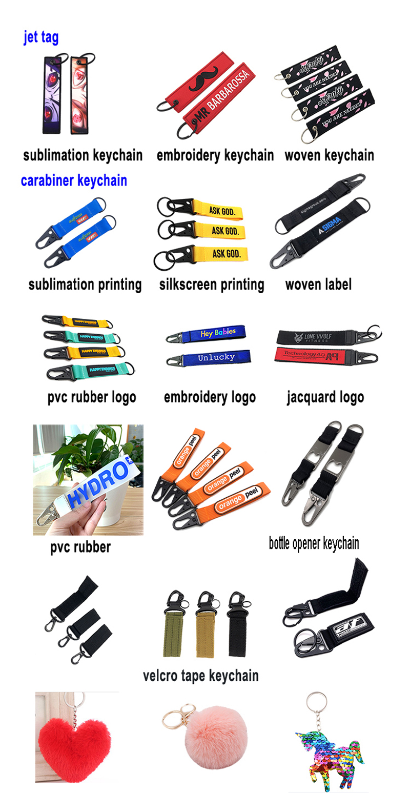
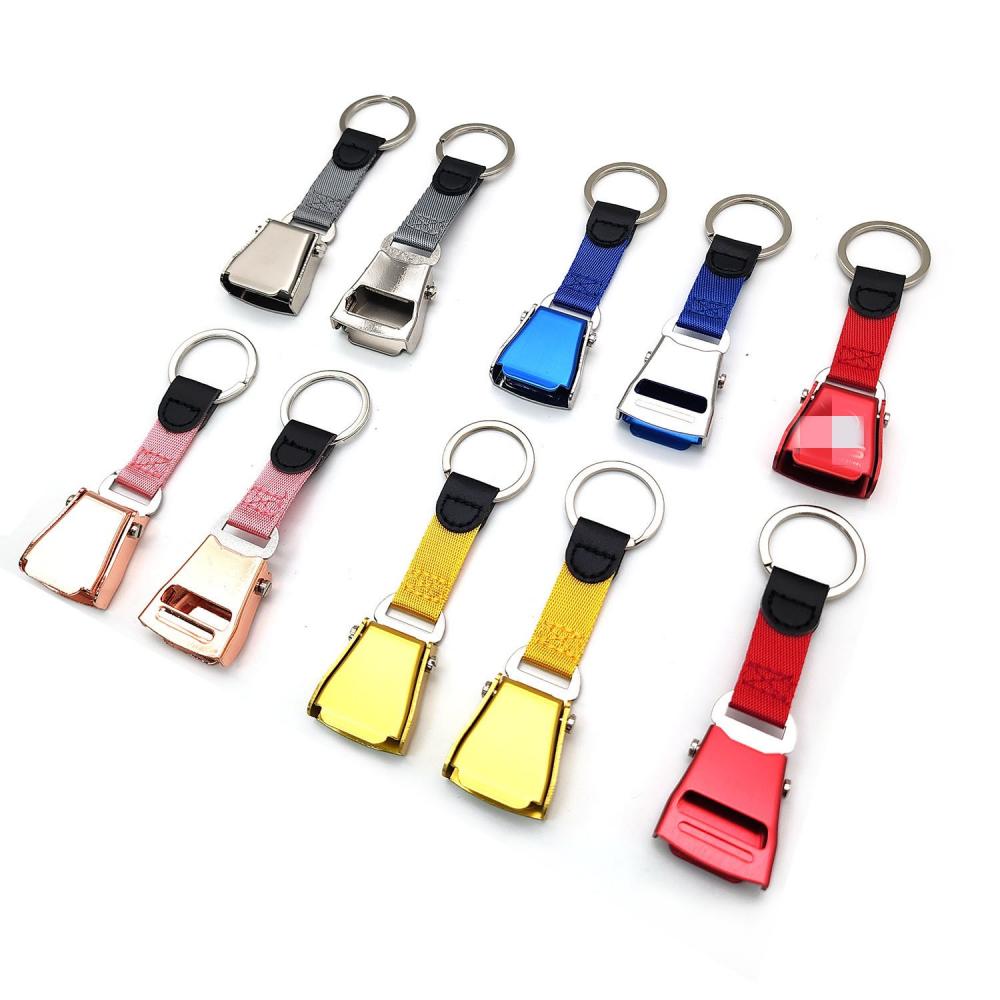
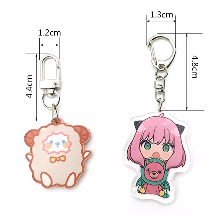
A Keychain is a small part usually made of various materials such as metal, acrylic, rubber, PVC or plastic, used to attach keys and other small items such as wallets, mobile phones, gloves, etc. It usually has a loop or hook that can be attached to the key so that it can be carried or removed. Customised Keychain designs and materials vary by brand, model, and personal preference, but they are generally functional and aesthetically pleasing.

The use of the Keychain Custom is very convenient, it can be conveniently hung on the key, so that the key is not easy to lose. Different styles of Custom Key Chains and keys have different effects, and can be used in various ways in daily life, such as connecting backpacks, handbags or clothing when going out, or connecting items when camping, traveling, etc. .


Custom Keychain designs and shapes vary by brand, model, and personal preference. SomeKeychains For Women will be printed with brand logos or cartoon images to increase their aesthetics and personalization. Some high-end Custom Key Chains also feature high-quality materials and fine craftsmanship to reflect their quality and value.
Keychains,Customised Keychain,Keychain Custom,Keychain Customized,Custom Keychain
Shenzhen Yiyixing Zipper Manufacture Co.,Ltd , https://www.yyxchina.com