Analysis of 200 liter steel drum round crimping process (4)
Tianjin Tiexie Metal Container Committee Wu Tielin
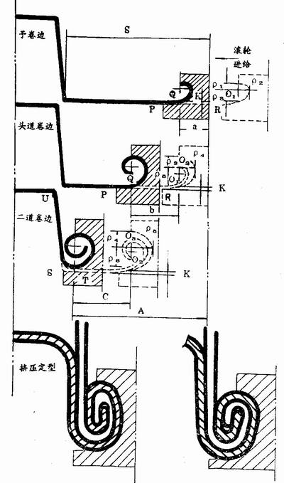
3. The crimping process analysis diagram, Figure 14.

Figure 14 Analysis of the crimping process
Through the previous discussion, we have a certain understanding of the hemming process, and now through the process analysis chart, quantitative analysis of each reeling.
(1) Pre-hem
The roller is fed in the horizontal direction. At the point R, the bottom cover enters the guide section and is lifted upward. K is the slope of the guide segment, that is, the height from the bottom edge when starting the curl (the vertical height corresponding to P and Q). Ρl, Ï2, Ï3 are Ï€, 1. The polar diameter corresponding to SÏ€ and 2Ï€. The roller curve is the steel barrel curling curve, and the line segment corresponding to π―2Ï€. The unfolded length of the roller curve is α, and a is also the stroke of the pre-rolling roller feed. Because the pre-roll is a single layer of curl, the force is small and does not affect the deformation of the bottom cover near the chassis of the crimping machine.
2) The first side of the roll
After the qualified barrel and bottom cover are fed into the crimping machine, the head roller starts to feed. At the stroke A-α, the pre-rolled PQ section and the head track roller PQ section coincide, and the pre-rolled portion enters the head track rolling groove, and is deformed along the deformation section after the Q point. Ρ3, Ï4, and Ï5 are polar axes corresponding to 2Ï€, 2.5Ï€, and 3Ï€. The curve of the roller is the corresponding line segment of the steel barrel curling curve 2Ï€-3Ï€. The curling deformation process is in the order of Ï5, Ï4, Ï3. During this time, the shape of the pre-hem portion is unchanged, except that the O point of the pre-rolled edge rotates counterclockwise. When the head roller is finished, the pre-rolling edge is rotated by 180°, and the roller curve can be obtained by Ï=αθ (2Ï€-3Ï€ interval). The unfolding length is b, which is also the feed stroke of the head roller. The PQ segment deformation is retained after the crimping is completed. In order to make the pre-rolling and the head-rolling edge connection accurate, the pre-rolling and head-rolling rolls must have the same K value and the PQ section must be the same. This is very important. Otherwise, the deformation cannot be continuously connected.
(3) two rolling edges
At the stroke (Aab), the head side curling PQ section and the second rolling PQ section are combined by the head side and the bottom side of the head roller. The two rollers are fed, the sides of the barrel and the bottom cover continue to curl, and finally the curved shape of the two rolls. It is a line segment corresponding to the steel barrel curling curve 2.5Ï€-3.5Ï€, wherein 2.5Ï€-3Ï€ is the repetitive head roller curling part, which has a good effect on overcoming the rebound and stabilizing the curling shape. Ρ4, Ï5, and Ï6 are polar diameters corresponding to 2.5Ï€, 3Ï€, and 3.5Ï€. The stroke C of the two-rolling feed is also the unfolded length of the 3Ï€-3.5Ï€ line segment of the steel barrel curling curve. The difference between the two-roller curl pre-crimping and the head-rolling curling edge is that there are no more PQ segments. When the guiding segment reaches the T point, the bottom cover edge receives a force perpendicular to the guiding segment and deforms along the guiding segment to continue curling. At this time, if the K value is too large, it is easy to form a dead point at the S point, and the ideal curve cannot be rolled out. It can be seen that the size of K is important. The pre-rolling, the first side curling, the two-roller roller guiding section K values ​​must be equal, and the size is determined by two crimping rollers.
In the first round of the curling process, the chassis (horizontal) or the barrel (vertical) must be given a sufficient axial force during the two crimping processes. The axial force enables a horizontal component (radial component) to be fed in the flanged portion of the barrel to make the roll dense. The axial force causes the S point to be subjected to an upward pulling force, and the bottom cover edge has a relatively upward movement relative to the barrel body, and the US section has a tensile phenomenon in the process. The S point is subjected to the tensile force of the vertical and the tangential direction of the guiding section (the inner layer already has the shape of the steel barrel curling curve), and the shape of the steel barrel curling curve between 3.5Ï€ and 4Ï€ can be substantially completed. That is to say, the 3.5Ï€ - 4Ï€ interval of the steel drum curling curve is not a crimp forming but a stretch forming.
If the roller has a certain feed force and continues to feed a small distance, the outline will change slightly for a period of time, that is, it will be squeezed and shaped, the curl will be compacted, and the impact resistance can be improved, and the four-folded edge can be eliminated.
(4) Extrusion shaping
After two rolling edges, the steel drum curl has been basically rolled into 6-7 layers, but it is still necessary to increase the extrusion setting. Its role is two: in the condition of the 6-7 layer of the film layer: get different shapes of the curling, avoiding the so-called patents of some companies. Establish the product type of the enterprise, distinguish the products of other enterprises; improve the curling strength of the steel barrel by the secondary deformation (again cold work hardening), and make the winding layer compact. Changing the shape allows the force to be reasonable during the drop test. It acts as a buffer when it falls. It can be seen from this that it is absolutely necessary to create a first-class product and increase the extrusion and shaping process.
4. Crimping process analysis conclusion
By expanding the length calculation, it is possible to know S, a, b, c and Ïl, Ï2, Ï3, Ï4, Ï5, Ï6. From this we can draw the following conclusions:
1 The pre-crimping, the first beading and the two beading have equal K values, which solves the continuity of each reeling edge.
2 Understand the realization process of the steel barrel curling curve of each section.
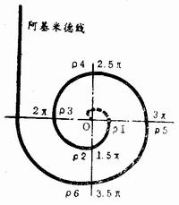
O-Ï€, reserved as a packing gap.
Î -2Ï€, realized by pre-crimping, once formed.
2Ï€ - 3Ï€, the first side curling is completed, one molding (2.5Ï€ - 3Ï€ is formed in the second rolling edge).
3Ï€-3.5Ï€, two rolling edges are completed, one molding.
3.5Ï€ - 4Ï€, stretch forming.
(In order to increase or change the fill line of the overmolding; the gap size of the material, you can choose different sections of the steel barrel curling curve, such as 1.5Ï€-4 redundancy, etc.)
3 Since the polar coordinate equation Ï=αθ of the steel drum curling curve is established, knowing the deformation process of each segment is equivalent to giving the roller curve (can be made). Find Ï1, Ï2, Ï3, Ï4, Ï5, and Ï6.
4 Since the feed distances a, b, and c of the roller are calculated, it is equivalent to giving the corresponding cam stroke, and the feed speed of the cam can be designed.
5 The curling shape, the roller curve, the cam stroke and the feed speed are linked by the steel drum curling curve, and then the whole wheel is not required to be thrown away, and the “universal†roller is pursued one-sidedly.
6 Using the above analysis method, the analysis method of the hemming process associated with the rounded edge of the circular curve and the curling shape of the mixed curve rounded edge, the roller curve, the unfolding length and the roller stroke can also be derived.
The above analysis is a theoretically concluded conclusion under fully idealized conditions. In the implementation phase, some data should be appropriately revised.
Analysis of the process of the seven-layer round crimping process of the Archimedes line steel drum:
1 There should be a gap in the bead of the steel drum to store the packing, and the O-Ï€ segment of the Archimedes line (actually 0-Ï€ segment is also meaningless) is used as the packing gap.
2 For the sake of easy drawing, only the bottom (cover) curling pattern is given.
8 bottom (cover) side width S a+b+c=A guide section slope is K
4 Archimedes line polar angle θ corresponds to the polar diameter Ï table.

Conference Interactive Whiteboard
As
a conference all-in-one machine, conference Interactive Whiteboard, microphones
and conference software. The small size contains great momentum, providing
high-quality pictures and sound effects for team video conferences.
In terms of camera hardware configuration, the
electronic Interactive Digital Board uses a 12 million pixel camera and
supports a wide viewing angle of 120 degree. It can be used in small and
medium-sized office spaces and can incorporate more team members into the video
conference scene. 4K high-definition resolution can provide high-quality video
images, adding points to the corporate image.
In terms of sound experience, interactive digital
board has built-in 6 array microphones to bring high-fidelity sound quality,
and conference interactive smart board can achieve up to 8 meters of remote
sound pickup, and can perform accurate sound in every corner of the meeting
room. At the same time, in the remote meeting mode, the tablet will locate the
sound source so that the speaker will not be able to display the picture, automatically gain the voice, eliminate echo and noise, even if the speaker is
far away, the audience can still hear it.
Conference Interactive Smart Board,Conference All-In-One Smart Board,Electronic Interactive Digital Board,Interactive Digital Board
Guangdong Zecheng Intelligent Technology Co., Ltd , https://www.szzcsecurity.com